Not meeting the desired aesthetic or functional standards? It could be due to poor surface finish, which can adversely impact both the visual appeal and the functionality of a part. Understanding this concept is a fundamental aspect of delivering high-quality parts.
Surface finish refers to the texture of a surface, and it is determined by the small deviations in height and pattern from a completely even surface.
Surface finish is important because the slightest variations can affect the quality, performance, or longevity of a part. Keep reading to understand how this is measured and achieved.
How To Measure Surface Roughness?
Surface roughness can be measured using one of three main categories of approaches: contact methods, non-contact methods, and comparison methods. Each method is suitable for different applications and material and offers a diverse level of precision and speed.
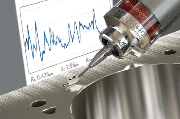
Contact Methods (Stylus Probe Instrument)
Contact methods involve the use of a stylus probe to trace the surface profile. The stylus physically touches the part, measuring the height of the surface as it moves across it. The method is highly useful in obtaining key roughness parameters such the Ra or Rz values.
Contact methods are highly accurate, but can be unsuitable for applications with delicate surfaces, as the stylus may cause damage. This method is most often used when measuring the roughness of metal or hard plastic surfaces.
Non-Contact Methods (Optical Light, Laser, or X-Ray)
Non-contact techniques use light or laser profilometers to scan a surface without making physical contact with it. For instance, laser profilometers project a laser beam onto the surface and measure the height variations. Optical and X-ray technologies can provide high-resolution data for analysis on delicate or complex surfaces.
These methods are faster than techniques involving stylus and are more suitable for measuring non-ideal surfaces, such as soft, elastic, or very small parts. They are often used in industries such as aerospace, electronics, and medical device manufacturing.
Comparison Methods
In comparison methods, the surface texture is evaluated by visually or tactually comparing it to standard roughness samples or reference charts. This provides a rough estimate of the surface finish rather than a precise numerical value. While less accurate, these methods are quick and inexpensive, making them suitable for preliminary assessments or routine quality checks in manufacturing.
Comparison methods are commonly used when a general surface texture assessment is sufficient, such as for low-cost or large-volume parts.
In-Process Surface Finish Measurement
Are you seeing variations in your measured surface finish data during production? It can be difficult to attain accurate real-time measurement but is critical for ensuring part quality.
In-process surface measurement accurately monitors part quality during manufacturing, minimizing the possibility of defects. The inductance method, machine probing, and ultrasonic methods are common techniques utilized in the CNC machining industry.
Real-time feedback is essential in ensuring that specified surface requirements are met before the part goes into production to curtail expensive reworks or delays.
Inductance Method
Are you struggling with non-contact surface finish measurement? The inductance method provides an accurate, non-invasive solution.
The inductance method measures a surface’s roughness by sensing changes in inductance as a result of height variations. It is suitable for applications that can prove problematic with contact methods.
Machine Method
The machine probing method is useful for high-speed production lines. This method directly integrates the assessment of surface roughness as part of the entire production process.
In this case, the CNC machine is fitted with built-in probes that conduct a realtime inspection of the surface under assessment. By capturing instant feedback, the part processing parameters can be adjusted in real-time.
The machine probing method is best suited for highly-automated production environments where efficiency, throughput, and quality are at the utmost importance.
Ultrasound Method
Need a way to measure surface texture on difficult-to-reach areas or complex geometries? Ultrasound methods offer a viable solution.
The ultrasound method uses high-frequency sound waves to measure surface texture. It is ideal to use when inspecting the quality of an uneven or irregular surface when other traditional methods are quite impractical to use.
It is often used to inspect the surface finish of intricate and complex components found in the aerospace and automobile industries.
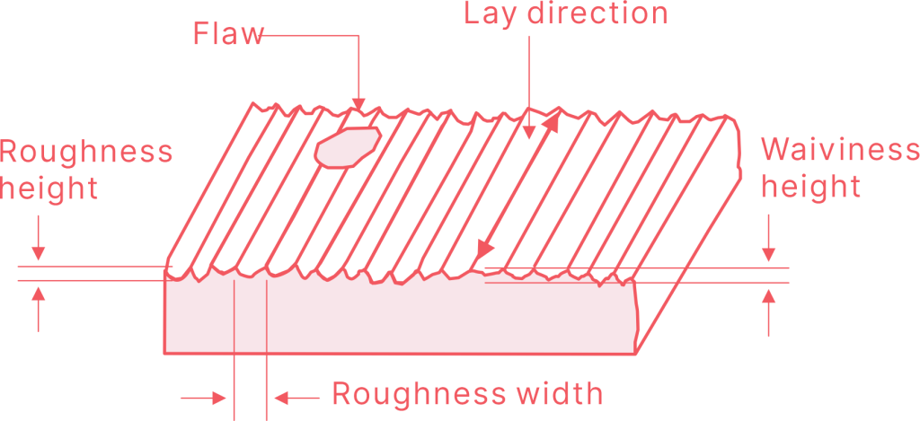
Surface Roughness Terminology
Surface roughness is measured using several parameters, each denoting different characteristics of the surface texture. Understanding these key terms is paramount in specifying and achieving part surface finish requirements in CNC machining.
The most common parameters used for surface roughness measurements include:
Ra – Average Roughness (Center Line Average)
Ra indicates the average deviation of the surface profile from the mean line over a sampling length. It provides a general indication of the surface finish quality. Lower Ra values correspond to smoother surfaces, whereas higher Ra values correspond to rougher textures.
Rz – Average Maximum Height of the Profile
Rz is the average of the highest peak-to-valley distances measured within several sampling lengths. It’s calculated by averaging the largest vertical distance between the highest peak and lowest valley for each sample.
This parameter is useful when you want to understand the overall height of the surface irregularities.
Rp – Maximum Peak Height
Rp is the height of the highest peak within the sampling length, and gives insight into the sharpest or most extreme points on the surface. This is essential to ensure that overemphasized peaks are not present on the surface, which could affect the part’s functionality or assembly.
Rv – Maximum Valley Depth
Rv represents the depth of the deepest valley within the sampling length, which identifies the lowest point of the surface profile. This characteristic is essential as it provides an understanding of areas where the surface dips excessively.
Rmax – Maximum Roughness Depth
Rmax represents the vertical distance from the highest peak to the lowest valley within the sampling length. It highlights the most extreme deviation in surface height, giving you a clear idea of the roughest points on the part.
This parameter is useful in applications where even minor surface imperfections can lead to significant issues.
RMS – Root Mean Square
The RMS (Root Mean Square) value is another residual measurement that indicates the statistical value for surface roughness. The calculation of this value takes the square root of the average of all the squared distances from the mean line. Although very similar to the Ra formula, the RMS formula tends to place a higher emphasis on the larger deviations from the mean line.
What Are the Common Surface Finishes in CNC Machining?
Common surface finishes in CNC machining include as-machined and a variety of post-processing technologies such as bead blasting, anodizing, powder coating, and polishing. Each of these finishes serve a specific purpose and offer different advantages based on the material and part’s application.
1. As-Machined Finish
The as-machined finish refers to the condition of the part surface as it comes out of the CNC machining process before any additional finishing operations are applied. This surface finish frequently exhibits visible tool marks and minor roughness, resulting in a surface roughness value of about Ra 1.6 to 3.2 µm.
2. Bead Blasting
Bead blasting uses high-pressure air to apply fine glass beads or other abrasive material to the surface. This process gives the part a smooth matte finish that is aesthetically pleasing and uniform throughout the part. Bead blasting also eliminates any surface imperfections and even removes machining marks.
3. Anodizing
Anodizing is an electrochemical process that converts the metal surface, primarily aluminum, into an oxide layer for increased corrosion and wear resistance. Anodizing also allows for various color options.
4. Powder Coating
Powder coating is the process of applying a dry powder onto the part surface and then heating it to form a hard, protective layer.
The finish achieved with powder coating is thick and resilient against corrosion, chemicals, and damage. Additionally, powder coatings are available in a variety of textures and colors.
5. Polishing
Polishing is a surface finishing process that utilizes fine abrasive grains to achieve a smooth surface, often resulting in a reflective, mirror-like surface finish. Although polishing is often practiced for aesthetic purposes, it can also be useful in reducing friction and ensuring cleanliness. Polished finishes usually have a roughness below Ra 0.1 µm.
6. Brushed Finish
A brushed finish is achieved by brushing the surface with an abrasive material, which produces thin, parallel lines. The textured surface created by the brushing process can hide surface imperfections and imparts a semi-matte visual appearance.
RA Surface Finishes For Various Manufacturing Processes
The parameter Ra describes the average deviation of a surface from its ideal smoothness. Each manufacturing process results in a different range of surface roughness due to the materials, tool inserts, and machining techniques that each process utilizes.
The table below provides the average Ra roughness values for a selection of common manufacturing processes, giving you a better understanding of the range of surface finishes available.
Surface Roughness Conversion Chart
A surface roughness conversion chart simplifies this process, allowing manufacturers to convert between different international standards, such as Ra, Rz, and RMS, ensuring global consistency in product quality.
With this chart, you can confidently interpret surface finish specifications from different regions or industries.
Importance of Surface Roughness in CNC Machining
Is surface quality affecting your product’s performance or durability? Surface roughness directly impacts the functionality and appearance of machined parts.
Functionality: A smoother surface reduces friction and wear, which is crucial for moving parts, seals, or components involved in fluid flow. For example, smooth surfaces in engine components reduce heat and improve efficiency.
Durability: Rougher surfaces may have stress points that could lead to cracks, fatigue, or corrosion over time. Surface finishing improves a part’s ability to resist such failures, increasing its lifespan.
Aesthetics: Surface roughness can also influence the appearance of consumer products. A rough finish may not meet the visual quality standards of applications like electronics or medical devices.
Fit and Tolerances: High-precision parts with tight tolerances require smooth finishes to ensure proper fit and functionality without additional wear or gaps between mating components.
What Are The Factors Affecting Surface Finish?
Surface finish is influenced by factors such as tool condition, cutting speed, material properties, machine stability, and even environmental conditions. Understanding these variables is essential for achieving a smooth and consistent finish on CNC machined parts.
Let’s take a closer look at these factors and how they impact surface finish quality.
Tool Condition
A sharp, well-maintained cutting tool will create smoother surfaces, while a worn or damaged tool can cause defects, scratches, or chatter marks. Cutting edges that are dull or chipped increase friction, which degrades the finish and can lead to overheating and material deformation.
Regularly inspecting and replacing tools can significantly improve surface finish, minimizing the risk of defects and prolonging tool life.
Cutting Speed and Feed Rate
Cutting speed and feed rate have a direct effect on surface roughness. Faster cutting speeds can increase the temperature, causing thermal damage or warping, leading to poor surface finishes. Conversely, slower speeds may generate better finishes but can increase machining time.
Similarly, the feed rate needs to be balanced: a high feed rate often leads to rougher surfaces, while a slower feed rate typically results in smoother finishes but can reduce efficiency.
Material Properties
Material properties greatly influence surface finish. Harder materials, like stainless steel or titanium, tend to produce rougher surfaces unless machined with specialized tools or techniques.
Softer materials, like aluminum or plastic, can yield smoother finishes but are prone to scratching or deformation during the process. Additionally, composite materials or those with complex structures may require careful handling to avoid surface imperfections.
Machine Stability and Vibration
Any instability or excessive vibration during the cutting process can result in chatter marks, leading to rough or uneven surfaces. Poorly secured workpieces or loose machine components can exacerbate these issues, making it difficult to achieve a consistent finish.
Ensuring machine stability, using proper fixturing, and reducing vibration through controlled feed rates can lead to smoother surfaces and more predictable outcomes.
Environmental Conditions
Environmental conditions such as temperature, humidity, and dust levels can impact surface finish. Changes in temperature can cause thermal expansion in both the material and the cutting tools, resulting in variations in surface texture.
Excessive heat during machining can also affect surface quality, causing discoloration, warping, or oxidation. Using coolants, proper ventilation, and maintaining a stable workshop environment can help mitigate these effects.