Increase your knowledge about common welding defects so you can avoid them as much as possible or notice them immediately for timely fixing.
Any unacceptable imperfection or defect in the welding process can immediately be defined as a welding defect. In this article, you will be able to analyze different welding defects elaboratively. You will even know the different types of welding defects and the possible causes and remedies for them.
What is a Weld Defect?
A weld defect refers to any flaw, imperfection, or irregularity developed in a provided weldment, which will eventually compromise the tools’ aesthetic appeal or intended use. Any irregularity that may compromise the weld falls under weld defects.
It differs from weld discontinuity, which refers to a flaw that won’t compromise the weld. The defect may differ in shape, extent, and size depending on the welded structure of the metal as well as the actual welding procedure.
In most cases, the causes of these defects are incorrect welding patterns or methods. Note, though, that other factors can also cause certain flaws in a weldment.
Another thing to note about weld defects is that they may occur internally or externally. This means that they could be outside or inside the weld metal. Regardless of where they are, there’s a big chance that they may cause weakened joints and appearance.
Also, take note that while a few common welding flaws are within the limits permitted by law, others may potentially result in product rejection. With that said, it is truly significant to prevent any weld imperfection or failure.
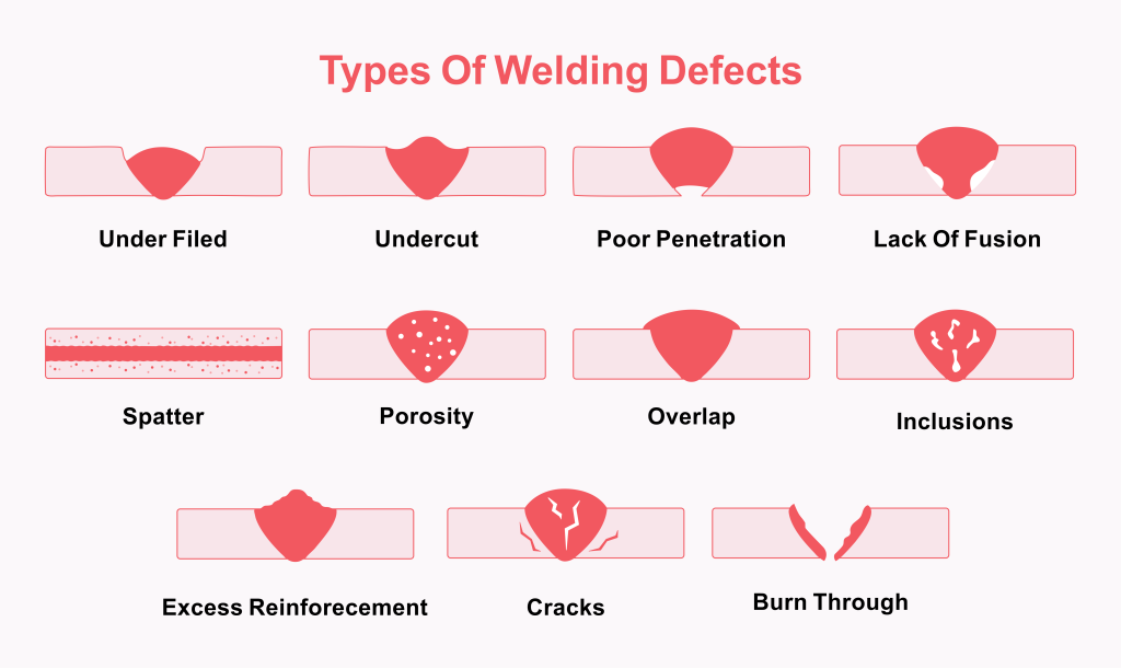
What are the Common Weld Defects?
Now, it’s time to learn the most common weld defects and faults that are often categorized based on their actual location while inside the metal. A weld defect could also be internal or external.
External Welding Defects
An external welding defect can be defined as a visual or superficial defect. It manifests on the metal weldment’s surface. In most cases, you can detect external weld defects through visual inspection. You can also use other methods, like dye liquid penetrants (DPI) and magnetic particle inspection (MPI).
To gain a much better understanding of what an external welding defect is, here are its most common types:
#1 – Porosity
Otherwise called wormhole welds, defects associated with porosity occur if there are entrapped gas or air bubbles within the weld. Note that the process of welding usually generates gases, such as carbon dioxide, steam, and hydrogen.
Meanwhile, porous weld beads’ cross-section can often be seen as resembling a sponge but with accumulated air bubbles trapped inside. It would be likely for the entrapped grasses to be localized in a certain spot. It is also possible to distribute them uniformly in the weld.
Such gas bubbles may cause the weld metal’s joints to weaken, thereby prompting damage and fatigue. Also, depending on the weld’s formation, it is possible to enjoy orbital welding errors.
Causes of Porosity
Using an insufficient coating of electrode – It could also be that you use a corroded electrode, resulting in porosity
Occurrence of oil, rust, grease, hydrocarbon, or water on the surface of the weld
Using incorrect or inappropriate shielding gas
Excessively high gas flow or arc welding voltage – Note that it should be around 15 to 30 volts only.
Poor base metal surface treatment
Preventing Porosity
Use low current only.
Use correct electrodes, such as medium carbon steels, weld bright steels, and alloy steels featuring low hydrogen electrodes.
Make sure that the electrode is dry. This is possible by keeping it in a dry and warm place.
Grind and re-weld where necessary.
#2 – Cracks
Out of all the welding defects, cracks are considered the most unwanted since they can have drastic effects on the weld surface. The cracks may appear on the surface, at zones affected by heat, or within the weld material.
Welding cracks can either be cold or hot. Cold cracks happen once the weld metal solidifies. Expect these cracks to develop a few days after the welding process is completed.
Meanwhile, hot cracks appear during the procedure or right after completing the welding. There is a high chance that it will take place once the molted weld pool solidifies.
Hot cracks are often visible in the weld metal, though, it is also likely for it to appear in the HAZ (heat-affected zone) region.
Causes of Welding Cracks
The base material has poor ductility.
Residual stress, which may cause the weld metal to crack
Rigid joints, making it hard to contract or expand the metals
High amounts of carbon and sulfur
The use of hydrogen as shielding gas as you weld ferrous materials
Preventing Cracks
Use appropriate materials when welding.
Preheat the weld and keep the cooling speed joint low.
Use reasonable weld joints to lessen the gap between each weld joint.
Release clamping force slowly as you weld as this can increase the welding material’s fill capacity.
#3 – Undercut
Another welding defect is undercut, which refers to irregular grooves shaped like notches visible at the base metal. Undercuts are highly likely to occur when the base metal melts away from the actual weld zone.
You can characterize undercuts based on their depth, sharpness, and length. Also, undercut defects found in welding can be seen running parallel to the weldment, resulting in the loss of their thickness.
This can further result in the weld joint becoming prone to fatigue. Undercuts come in several types, including continuous undercut, intermediate undercut, and inter-run undercut. It may happen if you keep on using the wrong filler material.
Causes of Undercut
Molten top edge resulting from the use of weld speed that’s extremely fast or a voltage that’s too high
Use of wrong filler metal
Incorrect electrode angle or electrode that’s too large
Wrong choice of shielding gas
Arc voltage that’s too high
Preventing Undercut
Use appropriate filler metal and gas mixture depending on the thickness and type of base metal.
Keep the power input and travel speed low.
Reduce arch voltage or length – Voltage has to be around 15 to 30 while the length should not go beyond the electrode core’s diameter.
Do the welding in flat positions.
#4 – Overlap
Also called overroll, the overlap is another welding defect characterized by the filler metal or material found at the toe of the weld covering the metal with no bonding. This causes the weld pool to flow in excessive amounts, further extending beyond the weld toe.
In this case, there’s a chance for the weld metal to create a less-than-90-degree angle.
Causes of Overlap
Incorrect welding technique used
Use of large-sized electrodes
Slow travel speed
Incorrect torch and varying electrode angle
High heat input or welding current
Preventing Overlap
Avoid using inappropriate or wrong electrode angle.
Use the appropriate and correct welding technique to achieve optimal arc length.
Try welding in flat positions and maintain the proper travel speed.
Do not use large-sized electrodes.
Use low welding current or heat input and use the right angle for the torch.
#5 – Burn-Through
Applying excessive amounts of heat as you do welding may cause the central part of the metal to have blown holes. This leads to the defect called burn-through, which commonly happens on thin metal sheets, specifically those with a thickness that does not go over one-fourth inches.
Burn-through may also happen on thicker metal stocks. This defect may occur in that case if the welding settings used are considered high or if there is slow torch movement.
Causes of Burn-through
Huge gaps in between each piece of metal
High welder settings used for thick metal
Slow torch movement
Incorrect sizes of welding wire used
Preventing Burn-through
Do not use a high welder or welding current setting.
Use tight sizes for the wires.
Apply optimal travel speed. In the case of MIG welding, it is crucial to maintain the travel speed at fourteen to nineteen inches every minute. Meanwhile, you should operate orbital welding equipment at four to ten inches every minute.
Do not use excessive gaps between each metal plate.
Do not use large angles for the bevel.
Make sure that there is enough hold-down and clamping of metal.
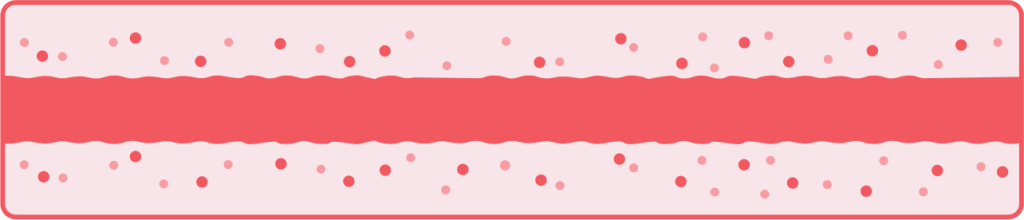
#6 – Spatter
Excessive spatter happens when tiny drops of molten metal or material stick to or scatter the metal around when the welding procedure is ongoing. It falls under the external weld defect classification if it goes beyond the specified amount.
In general, spatter does not threaten the structural integrity of the weld. However, it can detract from the finished work’s visual quality, which can drastically affect its perceived professionalism and overall aesthetic appeal.
The spatter defect is commonly found on MIG welding, though, it may also happen on other welding procedures.
Causes of Spatter
Amperage current setting that’s too high and voltage that’s too low
Incorrect shielding gas
Large arc length and wet electrode
Rigid electrode working angle
Metal surface contamination
Preventing Spatter
Select the right amperage to prevent hot settings.
Use appropriate volts. The voltage should not be too low.
The arch should remain short.
Set the correct polarity for the welding procedure.
Increase the angle of the electrode to improve control.
Make sure that the feed wire moves smoothly. It should also be devoid of any impediment.
#7 – Under Filled
Under filled refers to an external welding defect, which happens when there is a recessed weld bead beneath the base metal’s surface. This causes the joints to become weak.
In most cases, this defect looks like a longitudinal rut that you can find along the bead. It is also called a convex joint.
Causes of Under Filled
Improper or incorrect welding technology
High or fast welding speed
Low welding current
Wrong placement of the weld bead
Thinly laying the weld beads in welds with multiple passes
Preventing Under Filled
Reduce travel speed, thereby allowing the proper filling in of the weld pool.
Pick the right size for the filler wire or electrode.
Use the correct setting for the current, ensuring sufficient fusion.
Fill the weld to the appropriate level by making multiple passes.
#8 – Excess Reinforcement
This external weld defect takes place when there is an excessive amount of filler material inside the weld. Most project codes and specifications have limits in terms of the reinforcement’s height.
Oftentimes, it is capped at 3 mm or less over the parent metal.
Causes of Excess Reinforcement
Excess or inadequate flux amount on the feed wire
Varying settings for the voltage
Uneven or extremely fast feed wire travel speed
Large gaps left in between each weld piece
Preventing Excess Reinforcement
Ensure that the torch moves at the right speed.
Set the correct amperage and prevent the release of excess heat.
Align the pieces of weld to avoid big gaps.
Adjust volts to keep it at an optimal level.
#9 – Mechanical Damage
Mechanical damage is another type of welding defect characterized by the physical harm incurred by the weld bead upon completing the welding process. Several tools can cause this kind of defect, including chipping hammers, accidental impact caused by heavy objects, and grinders.
In most cases, mechanical damage happens due to work environment conditions or post-weld handling. This makes it different from other defects that happen while the welding process is still ongoing.
Causes of Mechanical Damage
Wrongly or improperly handled electrode holders
Inefficient use of the grinder
Application of extra force at the time of chipping
The arc was not engaged to the metal.
Preventing Mechanical Damage
Take extra care as you clean a weld joint or remove a slag as extremely aggressive methods may cause harm to the weld bead.
Do not deliver heavy and huge blows of the hammer to the weld as it may only lead to cracks or deformities.
Keep the weld protected from the possibility of being ground over or impacted by huge metal pieces. This is especially possible in hectic work environments with several tasks being accomplished.
#10 – Distortion
Also called warpage, distortion happens if you apply excessive amounts of heat during the welding process. This may change the dimensions and positions of metal plates.
Distortion has four classifications – fillet, angular, neutral axis, or longitudinal. Expect the distortion defect to become more visible and pronounced when it happens on thinner plates.
The reason is that this comes with a limited surface area, which may hamper the effective dissipation of heat.
Causes of Distortion
Slow speed for the arc travel
Varying temperature gradients while the welding process is still ongoing
Wrong welding order
High residual stress incurred by the welded metal plate
High number of welds pass that only have small diameter electrodes
Preventing Distortion
Use the appropriate amount of weld metal. This should help lessen contraction force.
Use the correct temperature gradient.
Arc travel speed should be maintained at ten to twenty inches every minute if you want to rotate workpieces and around four to ten inches every minute if you are handling orbital welding equipment.
Optimize the sheet metal part’s design, so it can get a sufficient number of weld passes.
#11 – Misalignment
There is also what we call misalignment, which may happen when the metals are improperly positioned during or before a welding operation. It is a problem as poor metal alignment makes the material prone to fatigue conditions. This is especially true if you decide to use it in pipe welding.
Causes of Misalignment
Operating the welding process too quickly
Wrong alignment of metal – It could also be that you were not able to secure the metals properly.
Inadequate skills of welder
Preventing Misalignment
Do a more stable and slower welding procedure.
Keep the metals firmly secure during and before the welding operation.
Never use inappropriate and wrong welding technique. Make it a regular habit to conduct checks, too.
Internal Welding Defects
Other welding defects can also be classified as internal. A few examples of internal welding defects are the following:
#12 – Slag Inclusion
Slags or any other hazardous byproducts may also emerge in several processes – among which are shielded metal arch, submerged arch techniques, and flux-core arc. In most cases, these slag inclusions look like trapped impurities on the welded areas’ surfaces or inside them.
In most cases, slags develop if you use a solid shielding material called flux during the process of welding. Expect the defects to come out once the flux melts on the weld’s surface or inside its weld region.
One problem with slag inclusions is that they can hamper the toughness and weldability of the metal, causing poor structural performance.
Causes of Slag Inclusions
Letting the weld cool too quickly
Wrong angle of the electrode
Use of just a small density for the welding current
Improperly cleaned weld layers
Rapid welding speed
Inadequate space for molten weld puddles
Preventing Slag Inclusions
Make the necessary adjustments for the travel rate of the electrode and its angle.
Raise the present density so it will come at the right angle.
Clean the surfaces of the weld bed before you deposit another layer.
Make sure to prevent too rapid cooling.
Maintain the right welding speed.
Redesign joints. The goal is to maintain enough space, so it can be properly used by the molten weld puddle.
#13 – Incomplete Fusion
This internal weld defect happens in case there is an insufficient bond between the base metal and filler material. The problem with lack of fusion is that it may cause structural weaknesses, such as gaps and voids.
Aside from the voids and gaps, the poor adhesion may also compromise the structural integrity of the weld.
Causes of Incomplete or Lack of Fusion
Metal surface contamination
Low heat input
Rapid travel speed
Incorrect or inappropriate electrode diameters for the specific thickness of the material
Huge weld pools that tend to move ahead of the weld arc
Preventing Incomplete/Lack of Fusion
Get rid of impurities by cleaning the base metal thoroughly.
Match the base metal by picking the right size of electrode and alloy.
Ensure that the torch speed remains steady. Avoid making it move too fast as it may only result in gaps.
Strengthen the bond by having sufficient amperage setting.
The arc length should be made suitable for the job.
#14 – Incomplete Penetration
As the name suggests, this type of internal welding defect happens when there is incomplete penetration of the weld beat at the butt joint’s bottom. It is a defect you should avoid or fix right away as it can have serious repercussions on the structural integrity of the joint.
Causes of Incomplete Penetration
Improperly aligned joints
Excessive space in between each weld
Rapid moving of the welding bead, which can lead to minimal metal disposition
Incorrect electrode positioning
The amperage setting is too low, which can prevent metal from melting adequately.
Preventing Incomplete Penetration
Pick the correct electrode size.
Prevent the weld puddle from moving too fast. It would be better to make it move slowly as it guarantees better penetration.
Ensure that the workpieces are carefully and properly aligned. This should help prevent irregular and large gaps that may only lead to improper penetration.
Keep an optimal amperage setting. Avoid keeping the current too low as it can cause poor penetration.
Other Welding Defects
#15 – Whiskers
Whiskers are among the most common welding defects that usually happen in MIG. Basically, they are characterized by short-length electrode wires that stick out of the weld, specifically at its joint root. In most cases, these happen due to a protruding electrode wire, which is derived from the leading edge of the pool.
Causes of Whiskers
Excessively high feed speed used for the electrode wire
Higher than necessary travel speed
Positioning the electrode ahead of the weld pool’s leading edge
Preventing Whiskers
The electrode wire should maintain a low feed speed.
Maintain an optimal travel speed. Ensure that it does not go too fast.
#16 – Necklace Cracking
This welding defect has a strong connection to electron beam welding. Necklace cracking is a form of poor or incomplete penetration, which may happen every time a molten metal has a hard time flowing sufficiently to the cavity.
Causes of Necklace Cracking
Incorrect or improper application of welding technique
Use of metals, including nickel-based alloy, tin, carbon steel, and stainless steel
Operating the electron beam welding at high speed
Preventing Necklace Cracking
Choose good materials when planning to do electron beam welding.
Make sure to apply correct and proper welding techniques
Focus on attaining uniformity with the use of constant speed.
How to Detect Welding Defects?
To detect welding defects, you can do non-destructive and destructive testing. Both work to help you uncover the presence of defects, which is beneficial if you want to fix such defects immediately.
Non-destructive Testing
With the help of non-destructive testing, you can spot weld discontinuities without any damage. It works well for high-speed production that only requires testing a sample from a batch.
You can often do non-destructive testing and evaluation through visual inspection. You can also use eddy currents, magnetic particles, liquid penetrants, emissions, radiography, and ultrasonics for the testing process, helping you spot weld discontinuities.
Destructive Testing
In the destructive testing method, you can gather information if you subject the completed projects to highly rigid techniques. You can do this until the projects reach their limitations.
There are instances when you need to do both destructive and non-destructive testing. This is to lessen weld defects significantly during production.
Among the destructive testing techniques that you can use to detect the weld metal’s limits are free bend, tensile strength, nick break, back bend, acid etch, and guided bend.
Conclusion
Welding is a process that you have to do carefully and correctly if you want to avoid defects that may have serious repercussions on the finished material. The types of welding defects indicated in this article should enlighten welders regarding the significance of getting the basics right and using the right welding technique all the time.
Ensure that you are aware of the foundational elements capable of distinguishing a defective weld from a reliable and strong one. Also, if you discover any welding defect, it is a must to fix it immediately. This can help boost your chance of saving the structural integrity of the weld.